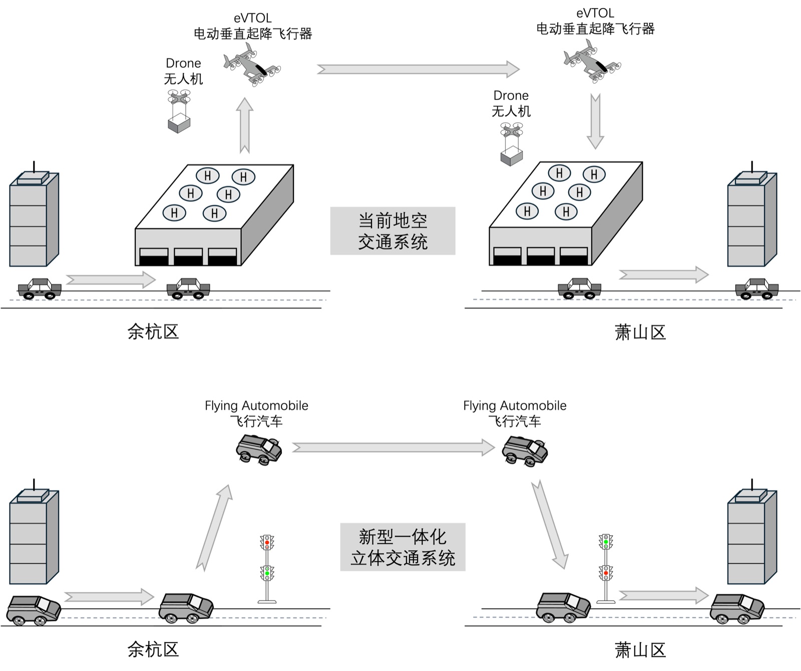
Whenever people talk about flying cars or urban air mobility, the conversation usually gravitates toward propulsion and battery density. When our team started working on Modeling and Simulation of a New Integrated Multilevel Transportation System, however, the question that kept us up at night was a traffic-engineering one: if surface roads and multiple low-altitude flight levels are stacked into a single city grid, how does a vehicle climb from Level 2 to Level 3 at a busy intersection without colliding with through-traffic above or below?
Without a unified set of junction rules governing both horizontal turns and vertical transitions, flying cars are stuck ferrying between isolated pads rather than operating as a continuous network. In this post, I want to walk through how we decomposed the system using Model-Based Systems Engineering (MBSE), follow a single vehicle through a multilevel intersection, and draw a clear line between our completed SysML models and the performance targets that still await simulation.
中文版本: 新型一体化立体交通系统:从路口调度到跨层通行
1. Breaking a 3D traffic network into three subsystems
To keep the architecture manageable, we split the overall system into three top-level domains: the flying car itself, the multilevel junction infrastructure, and fault handling with self-recovery. By our midterm milestone, we had completed the structural models for both the vehicle and the infrastructure, while fault handling remained at the use-case and framework stage.
Flying car: onboard sensing and safety envelopes
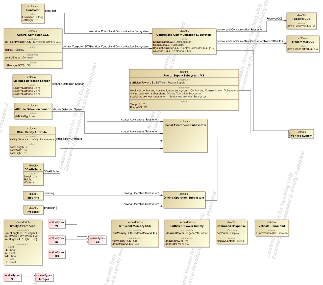
We modeled a rotorcraft-style roadable aircraft as our reference vehicle and divided its onboard architecture into four subsystems:
- Energy support: powers avionics, sensors, and propulsion, with power constraints captured explicitly in parametric diagrams;
- Control and communications: handles dispatch links and pilot inputs using a primary flight computer backed up by a redundant secondary unit;
- Motion: coordinates ground drive, airborne cruise, and vertical climb/descent corridors;
- Spatial awareness: pairs horizontal distance sensors with an altitude sensor, while an onboard storage module holds vehicle dimensions and minimum safety separation envelopes.
Infrastructure and junction control
Onboard sensors only see immediate neighbors; the intersection itself needs a global view. Our infrastructure model combines energy support, communications and data processing, and roadside sensing/signaling. Junction sensors monitor lane occupancy across every altitude layer, the central controller assigns conflict-free paths, and 3D traffic signals display both permission to enter and the authorized spatial corridor.
Fault handling and emergency recovery
On a surface street, a stalled car can pull over to the shoulder; in a low-altitude corridor, a propulsion fault affects every layer below it. In our use-case specifications, we designed an emergency response sequence: if a thruster fails, onboard sensors trigger an immediate broadcast of a fault code to expand nearby vehicles’ avoidance buffers, while dispatch clears the vertical descent path below and assigns an emergency landing zone. At the midterm stage, this recovery flow was defined in our use cases, with its detailed SysML Block Definition Diagram (BDD) queued for the next phase.
2. Following a flying car through a multilevel junction
To turn high-level concepts into testable logic, we traced a single flying car approaching and crossing a multilevel junction across six steps:
- Request permission 1 km out. As the vehicle approaches a multilevel intersection (using 1 km as our baseline trigger distance in the use-case draft), it reports its current altitude level and intended direction to junction control.
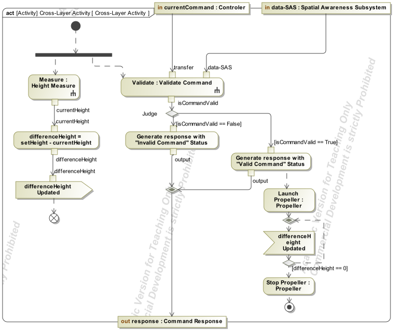
- Validate separation before engaging propulsion. Before executing any maneuver, onboard distance and altitude sensors check current separation against required safety margins. In our activity diagram, this acts as a hard gate: if separation falls short, the controller flags an invalid command and locks out the propulsion transition until the buffer is clear.
- Assign a layer or transition corridor. Junction control routes through-traffic along the main lanes of its current level, while turning or level-changing vehicles are directed into dedicated ascending or descending ramps.
- Follow 3D signal phasing. A red light holds traffic outside the conflict box; a green spatial arrow clears a specific 3D trajectory. Whenever a vehicle is cleared to climb or descend, conflicting streams on adjacent levels are held automatically.
- Execute a closed-loop altitude change. Inside the transition corridor, the vehicle climbs or descends while sampling its altitude sensor (modeled at a 5 ms loop interval in our activity diagram) until its measured height matches the target corridor.
- Merge and update lane load. Once the vehicle exits the junction into cruise mode, traffic control updates corridor occupancy and recalculates signal timing for the next wave.
We also included a load-balancing rule in the scheduling logic: whenever occupancy on a given level exceeds 90%, the controller adjusts signal phase lengths and diverts incoming vehicles to less congested layers.
3. Why we reached for SysML before writing simulation code
With a system this coupled, jumping straight into code or a 3D animation makes it very easy to miss hidden state conflicts. Following the MagicGrid methodology in MagicDraw (with 3DEXPERIENCE planned as our integration platform) forced us to separate the problem, solution, and implementation domains across four diagram families:
- Requirements and Use-Case Diagrams: capture safety rules and actor responsibilities between vehicles and dispatch;
- BDDs and Internal Block Diagrams (IBDs): define subsystem boundaries and the exact data/power ports connecting them;
- Activity, State-Machine, and Sequence Diagrams: lock down the command-validation gate, the 5 ms altitude loop, and transitions across stationary, takeoff, cruise, and landing states;
- Parametric Diagrams: bind physical parameters—layer spacing, corridor width, vehicle mass, and velocity caps—into mathematical constraints ready for downstream simulation.
4. Safety targets vs. unvalidated design inputs
In our use-case specifications, we wrote down concrete numbers to anchor the parametric model: a vertical transition speed cap of 2 m/s, horizontal turning acceleration under 1g, minimum separation of 5 m horizontally and 3 m vertically, command latency under 50 ms, a peak throughput target of 500 vehicles/min per junction, and a strict lockout of vertical transitions during severe weather.
When turning our project notes into a blog post, I want to be completely transparent about what those numbers represent: they are prior design inputs chosen to structure the SysML model, not validated outputs from a traffic simulator or hardware flight test.
5. Retrospective: what the model solves and what comes next
By the midterm review, our core achievement was turning a vague futuristic concept—“flying cars sharing a 3D intersection”—into a traceable SysML architecture with explicit safety gates and state transitions.
The next steps are equally clear: finishing the fault-recovery BDD, wiring up full multi-vehicle sequence diagrams, and feeding our parametric constraints into a microscopic traffic simulation to test whether a 5 m × 3 m safety envelope and a 2 m/s climb rate can actually sustain 500 vehicles per minute without gridlock. Defining those interfaces cleanly before claiming performance numbers is the most valuable habit I took away from this project.
Sources
This post is distilled from our project proposal, midterm presentation, use-case specifications, and SysML model files. All diagrams are exported directly from the project archive and retain their original Chinese labels.